
Field Repair Focus: XZ Drive Not Enabling
An XZ axis fault that appears immediately after machine startup can be difficult to isolate, especially when the servo drive has no local diagnostic LEDs and the primary information is shown at the NCU or CNC operator panel. A common symptom is that the drive-enable signal drops to zero, the axis is reported as inactive, or a protection-related message appears before any axis movement is commanded.
This type of fault does not automatically prove that the servo module has failed. The fault chain can include the PLC interlocks, CNC/NCU diagnostics, drive power and enable circuitry, motor power cable, encoder or feedback cable, motor connectors, and the motor itself. A structured diagnosis is important before replacing high-value CNC spare parts.
Start With a Safe Fault Record
Before resetting alarms or changing wiring, record the machine state. Capture the exact alarm number and text, time of occurrence, active axis status, NCU LED status, and any drive or PLC diagnostic screens. If the fault only appears once at startup and later changes to an "XZ inactive" status, the first event may contain the most useful information.
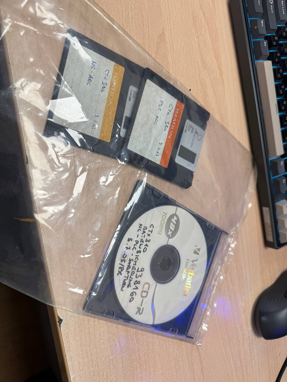
Create a backup of the current machine data, PLC project, parameters, and available archive files before restoring an earlier software version or making configuration changes. A previous archive may help compare a known-working state, but it should be restored only through the machine builder's documented procedure and with proper backups.
Useful information to collect includes:
- CNC, NCU, and servo module part numbers
- Motor type and rating, such as the applicable 1FK6 motor variant where fitted
- Complete alarm and error codes, including any 700xxx PLC-generated errors
- Whether the fault occurs at power-up, enable request, or axis movement
- Recent cable, connector, motor, cabinet, or software work
- Whether the Z-axis motor and wiring have been disturbed or remain untouched
Understand the 700-Series Error Path
Many 700xxx alarms in machine-tool environments are created by the machine manufacturer through PLC logic. They are often not a standard drive diagnosis by themselves. The number may represent a condition detected by the machine's safety chain, axis-ready logic, lubrication or hydraulic interlock, limit circuit, drive enable feedback, or another machine-specific signal.
The PLC project should therefore be reviewed to identify the alarm generation chain. Check which inputs, markers, function blocks, or status words trigger the specific 700-series alarm. The most important question is not only which alarm is displayed, but which condition prevented the PLC from maintaining the axis enable.
When reviewing PLC logic, verify:
- The drive enable command and the corresponding ready or enable feedback
- Emergency-stop and safety relay contacts relevant to the affected axes
- Cabinet power supply status and control-voltage monitoring
- Axis inhibit, machine mode, and reset conditions
- Feedback faults passed from the drive system to the PLC
- Any shared interlocks between X and Z axes
If the electrical automation sequence is correct and no logic condition is holding the axis off, attention should move downstream toward the servo module, cables, connectors, and motor feedback system.
Inspect Power and Feedback Connections Methodically
Intermittent cable or connector faults can produce startup-only alarms, especially where an axis cable flexes repeatedly or where the motor connector is subject to vibration, coolant contamination, oil mist, or mechanical strain. A previous improvement after securing motor power and encoder cables may indicate a movement-sensitive connection or cable defect, but it is not conclusive proof.
With the machine isolated and work performed by qualified personnel, inspect the motor power and feedback paths separately. Do not assume that a cable passing a basic continuity test is fault-free. Some failures occur only when the cable is bent, twisted, loaded, or affected by insulation breakdown under operating voltage.
Check the following areas:
- Motor-side power connector seating, locking condition, pin condition, and signs of overheating
- Encoder or feedback connector seating, shielding, pin alignment, and strain relief
- Cable routing near the motor, drag chain, cabinet entry, and sharp bending points
- Damage caused by repeated cable movement, crushing, coolant ingress, or abrasion
- Separation and shielding practices for power and feedback cables
- Cabinet-side connector condition and terminal tightness
- Motor housing, connector body, and cable gland damage
On some motor designs, connector orientation and permitted rotation can be limited. Do not force a connector beyond its specified range. If a connector can rotate approximately plus or minus 170 degrees, verify its mechanical position, cable strain relief, and contact integrity in the expected operating orientation.
Do Not Overlook the Encoder Supply
A motor may have sound power conductors while its feedback circuit is unstable. If the encoder supply cable has not been replaced or tested, it remains a reasonable inspection target. Loss of encoder power, poor shielding, connector contact resistance, or feedback signal degradation can prevent the drive from becoming ready even when no obvious short circuit is found.
Compare supply voltage and feedback status with the manufacturer's documentation and diagnostic tools where available. Measurements must be made using appropriate methods and safety procedures. Avoid probing or unplugging energized feedback circuits without confirming the equipment requirements, since incorrect testing can create additional faults or damage components.
Separate Cable, Motor, and Drive Module Causes
A controlled substitution test can be more useful than repeated visual inspection, provided the replacement part is correctly identified and the machine configuration supports the test. Possible approaches include testing with a known-good compatible cable, using an approved spare motor, or evaluating the suspected servo module through qualified repair or bench inspection.
Do not exchange motors, feedback cables, or drive modules solely on the basis of connector similarity. Confirm electrical ratings, feedback type, connector arrangement, firmware or parameter requirements, and machine-builder documentation first. A mismatch can introduce a second fault and obscure the original issue.
If the fault follows a particular cable or motor during an approved test, the source is likely in that assembly. If it remains with the same drive channel or cabinet location, further drive, power supply, interface, or PLC signal investigation is warranted.
Handling Archive Files and Previous Versions
Machine archives may be stored in formats such as .arc, but the extension alone does not identify the correct restoration tool. Some archives are generated by CNC service software or a machine builder's maintenance environment, while others may use general archive utilities. Inspect the archive source and associated documentation before attempting extraction or upload.
Do not assume that a general-purpose archive application is appropriate for CNC configuration files. Restoring an incomplete or incompatible archive can affect machine parameters, PLC data, and commissioning status. Confirm the archive type, software version, controller platform, and restoration procedure with the OEM, machine builder, or qualified CNC service provider.
When to Escalate for Parts Support
Escalate the case when the PLC logic identifies a persistent missing drive-ready condition, when cable and connector checks are inconclusive, or when a verified substitute points toward a motor, feedback assembly, or servo module.
For a quotation or technical confirmation, contact Vibocnc with the CNC/NCU model, servo module and motor nameplate details, all alarm codes, clear photos of connectors, and the troubleshooting results already completed. This information helps determine whether inspection, repair evaluation, cable replacement, motor sourcing, or a compatible CNC spare-parts option should be considered.